Crafting and Integrating Photorealistic Assets: A VFX Workflow Guide
Joe Williams shares a breakdown of his recent project from his second year at the NCCA – Bournemouth University, focusing on creating and integrating photorealistic assets into a background plate.
Joe Williams is a student specialising in creating photoreal hard surface assets for VFX. He is excited to share a breakdown of his most recent project from his second year at The National Centre for Computer Animation – Bournemouth University, creating and integrating photorealistic assets into a background plate.
Assignment Brief
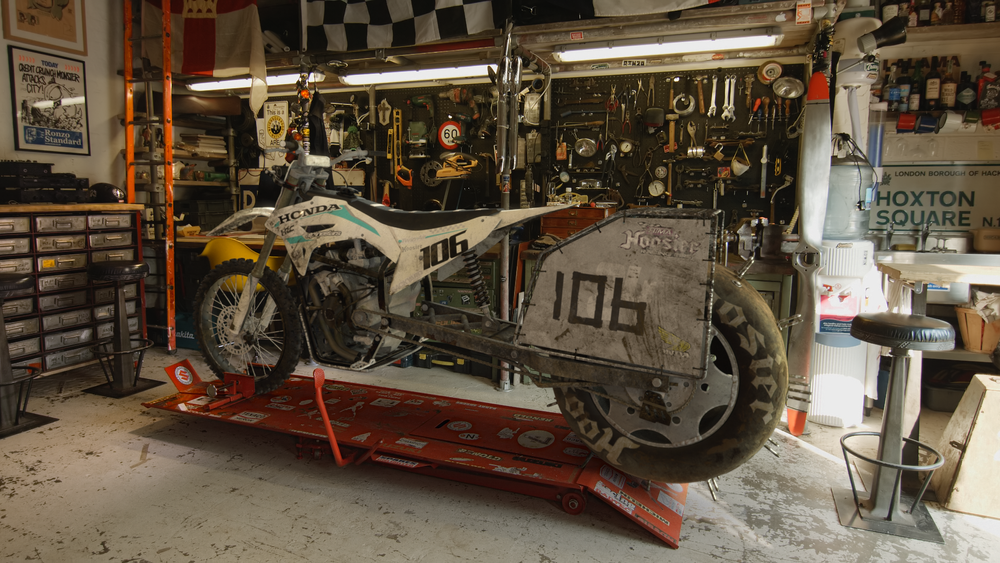
For this assignment we had to integrate a hard surface asset, with an emissive element, into the moving back plate provided.
Prior to finding out about the brief, I knew I wanted to make a motorbike as my next project. They serve as a great portfolio piece for hard surface modellers, as they have a range of types of surfaces across the model including; slick body work, mechanical engine, leather seat etc.
Inspiration and Reference
I was inspired by the French Hill Climb championship, where each rider designs their own bike which they ride up an extremely steep muddy incline. I referenced bits and pieces I liked from different bikes and came up with this design. My favourite parts being the 4 cylinder engine and the slick racing tyre with spikes. This was my first time collating references together into my own design, bearing in mind mechanical functionality.
My main reference was taken from various YouTube videos which showcase the hill climbing events. Mainly trying to take snapshots in the sections of the videos that show lots of close up shots of the bikes.
Moodboard and Reference
Blockout
I began blocking out the main frame of the bike, using the Honda CRF250R as my reference. Whilst doing this I encountered an issue; the 4 cylinder engine I chose for this design was MASSIVE and it did not fit the frame I referenced. After blocking in the engine I was able to mould the rest of the bike around that using a lattice deformer. This wasn't too much of a problem, as I was still working low poly.
Initial Blockout
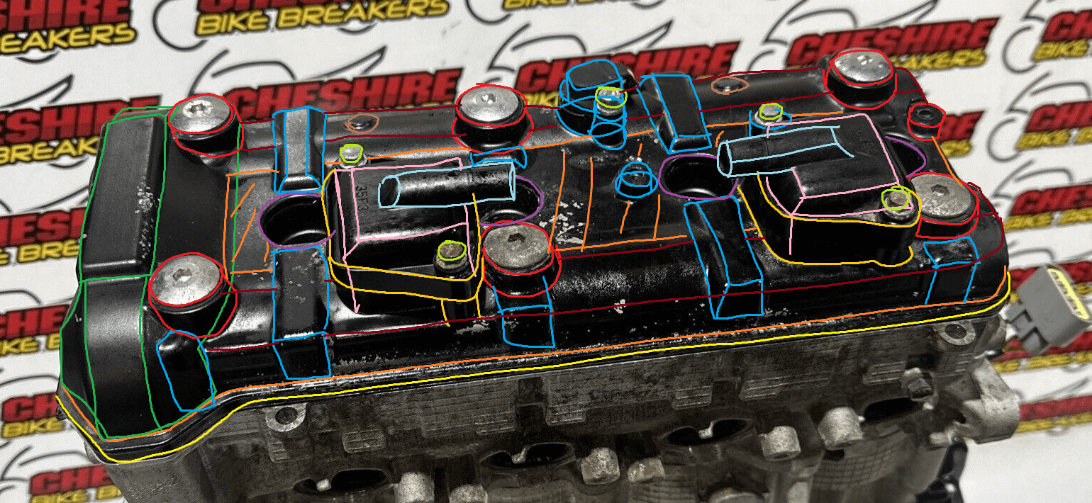
The main thing I focussed on was getting all the shapes in place and not worrying too much about topology. The engine was the hardest thing by far to wrap my head around. I took some of my reference images into photoshop and broke it down into primitive shapes. This helped me massively to understand and read my reference before trying to recreate it in 3D.
Breakdown of main shapes
Tracking and Layout Comp
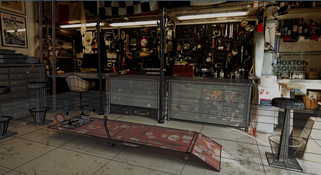
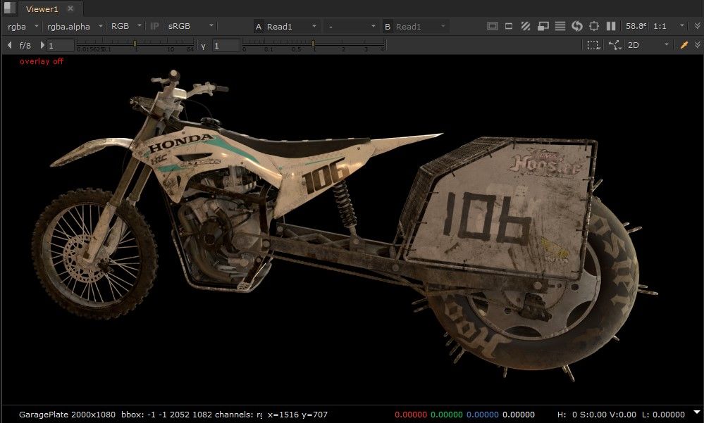
My tutor during this project was Ian Fellows, VFX Supervisor at Outpost VFX, and he taught me many valuable techniques to streamline my workflow. One of the things he suggested was to do a layout comp to make sure fundamentally the shot was working. This consisted of tracking the footage and rendering out a basic shader on the model with the tracked camera, and slapping it on top of the plate in nuke. This allowed me to discover any fundamental issues I had with my shot earlier on in the pipeline.
Layout Comp
Before tracking I had to undistort my footage using the lens grid provided with the back plate. This was straight forward, I simply used the lens distortion node in Nuke. I tracked my undistorted footage in PFTrack. I focused on creating user tracks on areas of the backplate where I needed accurate dummy geo. Since I had built my bike to scale, it was important to make sure the scene was scaled correctly. I was able to estimate the scale by researching the dimensions of objects I saw in the footage.
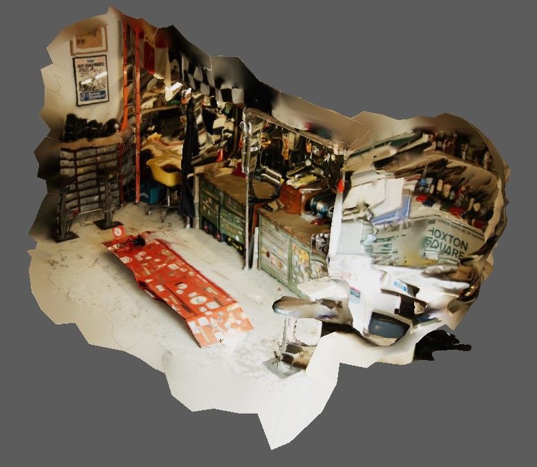
I created a quick photo-scan by processing the backplate through Agisoft Metashape. I initially thought I could use this instead of modelling dummy geo, but I found it to be too lumpy.
PhotoscanDummy Geo
Modelling
A huge inspiration of mine is an artist called Andrew Hodgson, Senior Hard Surface Modeller at DNEG Vancouver, all of his educational content across social media has been incredibly beneficial to me and has helped me so much over the last couple years.
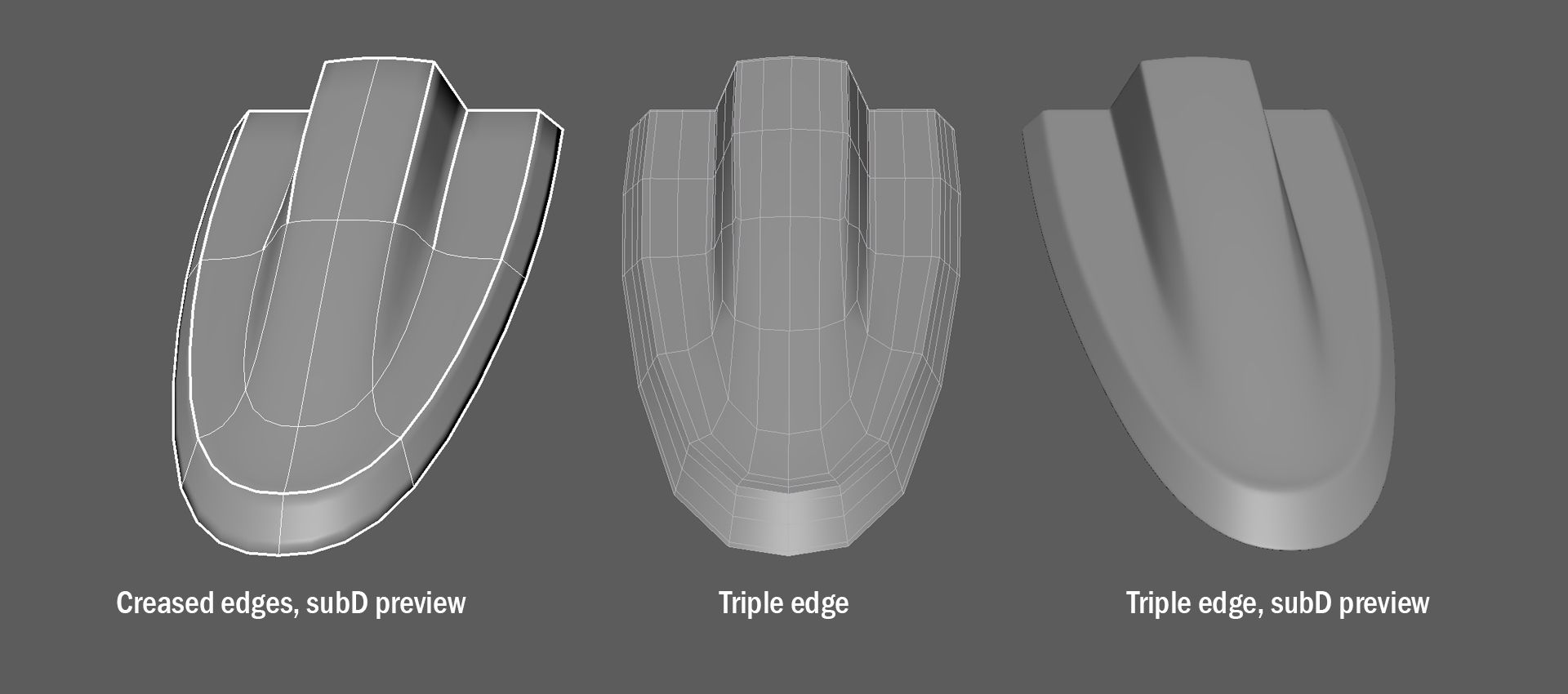
Andrew brought my attention to a workflow which utilises the crease tool in Maya when creating SubD models for VFX. This workflow consists of using low poly geo and creasing the edges to help maintain the shape when previewing the SubD. Once I am happy with my shape I subdivide the geo until it is the density I require and triple edge so it is SubD ready.
Crease modelling workflow
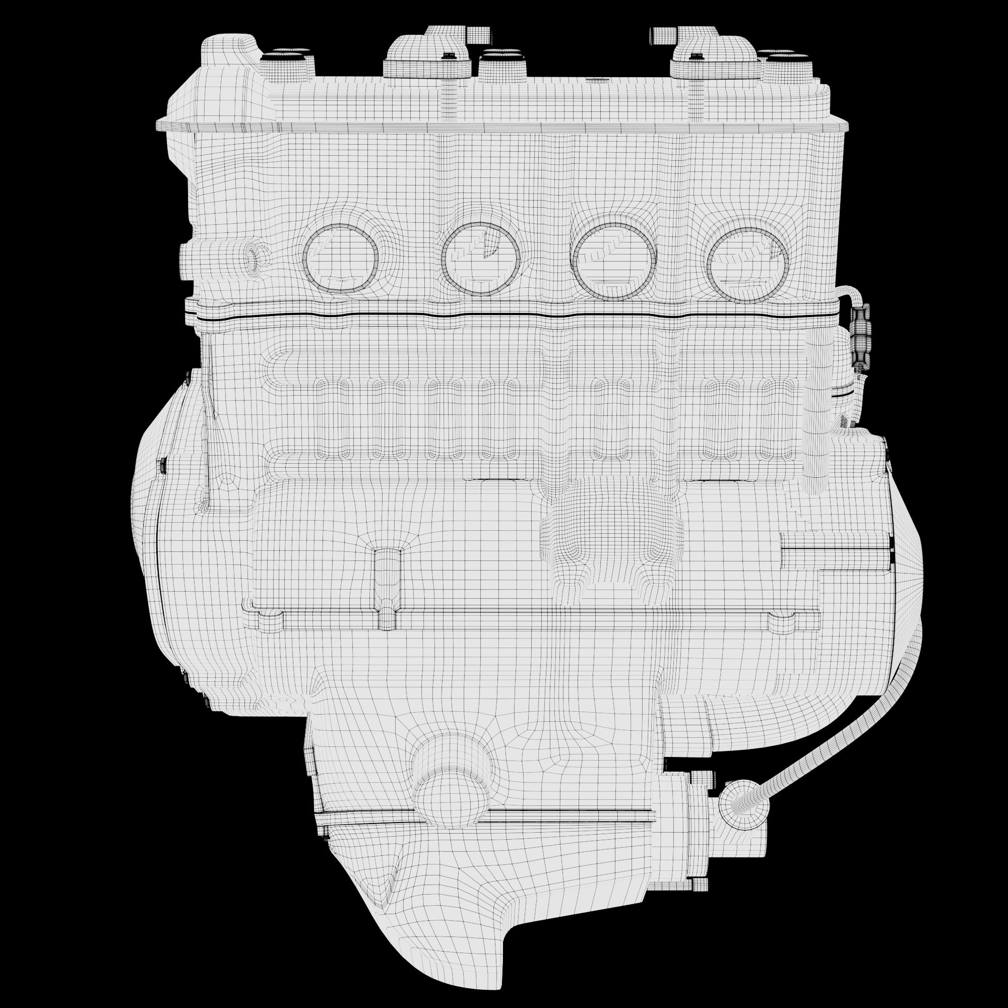
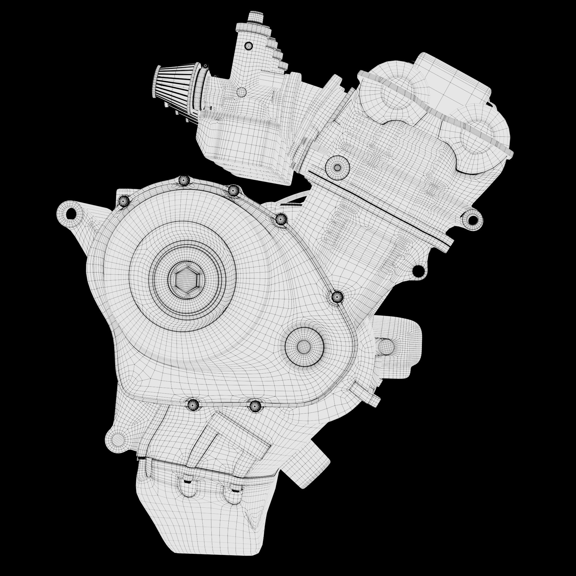
To challenge myself and push my topology skills, I initially decided to model the entire engine as one joined piece. The main way I was able to do this was using a technique called localised topology. This is the process of creating extra edge loops where it's needed and terminating them so that they don't run throughout the model. I think I did this successfully but I soon realised that I couldn't spend too long on the model as I still had a lot more work to do before the deadline.
I began to work a lot smarter and only put the extra model detail in where it needed it, as it was a lot quicker to simply combine and intersect extra details. My methodology for this was to properly model in details that dug into the surface, and intersect any extruded details.
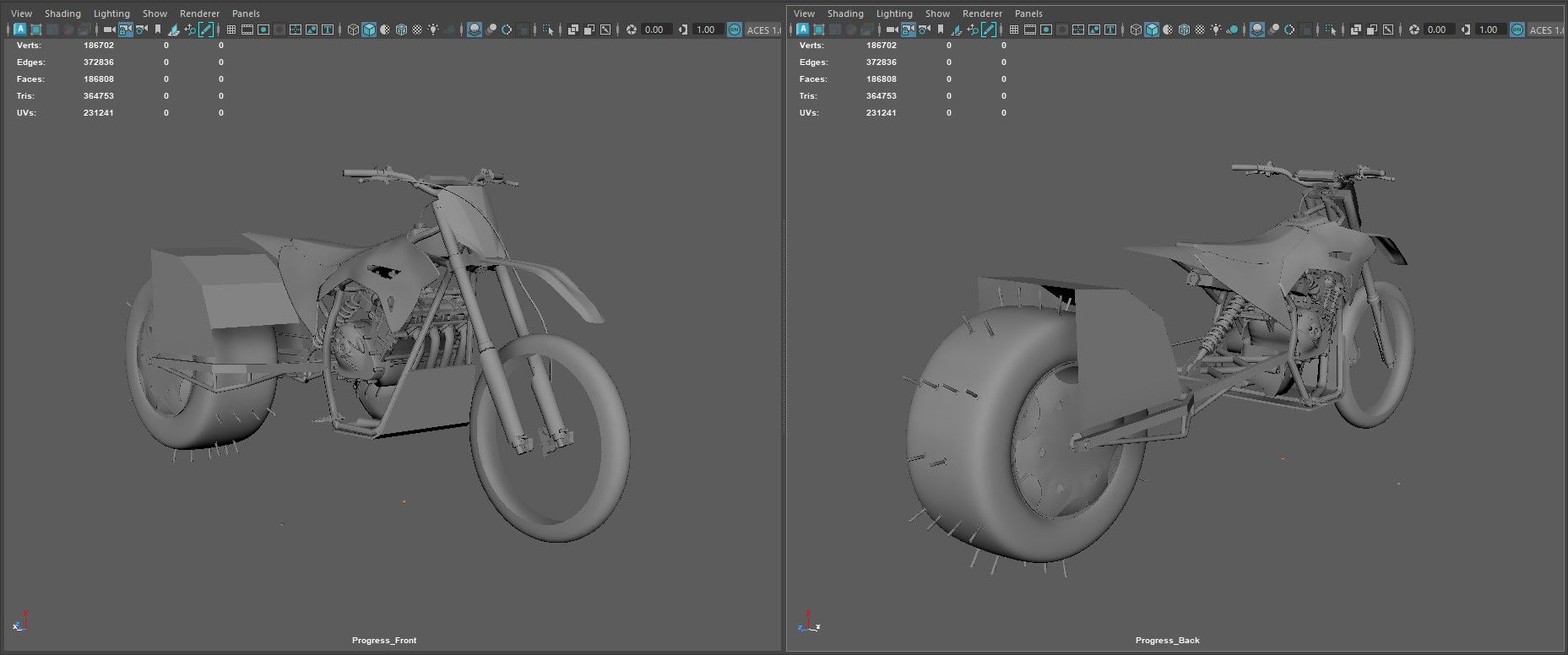
Engine wireframe with 1 subdivision
Naming Conventions and UVs
I tried to keep my naming and grouping of my geo clean and organised, even though I am not planning on rigging this asset, it feels like good practice to pretend it's going to be rigged by someone. I organised them into centre, left and right groups. Any geo in my left group was to be mirrored over to the other side, everything in my centre group wasn't necessarily in the middle of the bike, but I didn't need to be mirrored.
Although I didn't need a whole lot of resolution for the context of this shot. I opted to have more than I needed, as I have plans to do some close up renders in the future. I tried to layout my UVs in a way that would make selection masks a lot easier in Mari. Looking back now I realise that I could have optimised my UDIMs a lot more, as I have way too much empty space.
Texturing
I used this project as an opportunity to learn Mari to expand my texturing skillset and software knowledge. This was very exciting for me as I have heard so many good things about the software. My main two resources for learning were, Michael Wilde and Artruism Digital on YouTube. I found these both extremely useful for breaking the technical barrier when getting into this new software.
Before I jumped into Mari I baked my mesh maps in Substance 3D Painter. I wanted to use the new Mari bakery, unfortunately this wasn't available to me, as I only had access to Mari 5.0 on the university machines. After baking my AO and curvature I imported them into Mari through a paint node.
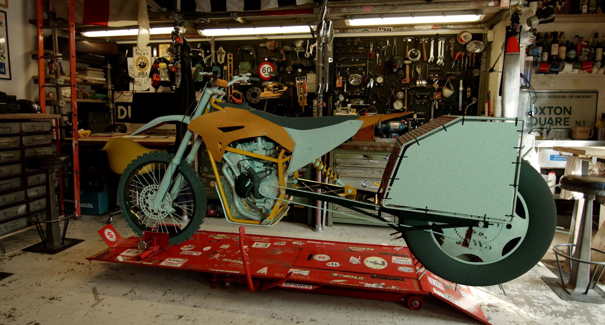
The first thing I did inside of Mari was create all the isolation masks I needed for each material, then applied a basic colour to each material to help visualise each one. From then on I went through each of my materials and started building them up. My main workflow throughout was to use basic colour nodes and drive all the complexities through the masks. This is more or less the exact same workflow I use in Substance 3D Painter, except in Mari, I get to utilise the power of nodes.
I tried to make most of the texturing procedural and only hand paint the hero details. This workflow proved to work quite well and allowed me to get a solid base quickly. Meaning I had more time to hand paint the hero details, which would stand out on this asset. The main details I hand painted was the dirt. I felt it was important that the dirt was placed in a way that would tell a story. I wanted the viewer to be able to imagine this dirt splashing and building up onto the bike. I was able to extract some dirt splash alphas from images I found on google, and painted them into the mask using the alphas as a stencil.
Mari viewport - dirt splashes
To create the secondary maps for this asset, I reused the masks from each material to drive a hsv node to control the value. I found using the teleport broadcast/receiver nodes were best for this as they would update any changes I made to my masks. I found changing my viewport background to a mid grey value helped me visualise my displacement maps.
Secondary maps node setup
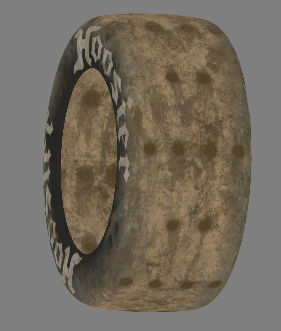
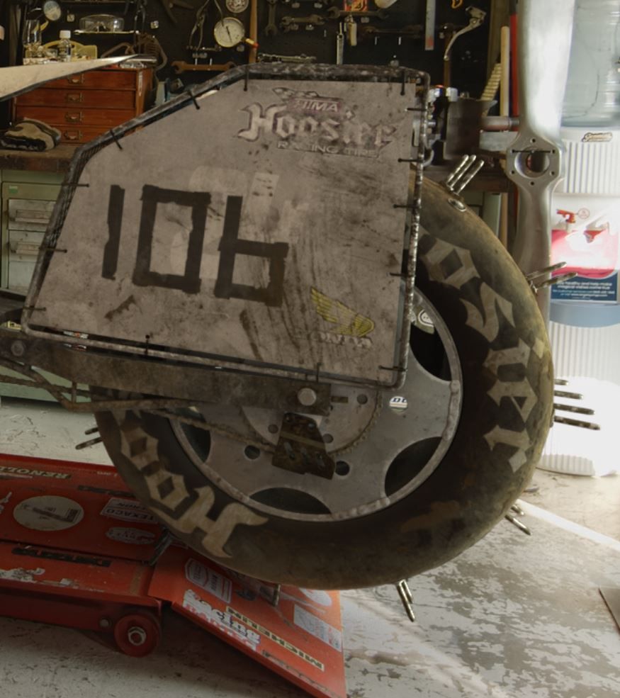
The biggest challenge when texturing this bike was the rear tire. It was one of the biggest features on the asset and I wanted to make sure it was well executed. I struggled at times with dialling in the displacement and breaking up the silhouette, due to the nature of the slick racing tire it lacked model detail.
I think if I was to go back now, I would take the displacement map into ZBrush and sculpt on top of it to create lots more variation and complexity in the dirt.
Mari viewport - rear tyre
I used a very small amount of displacement across most areas of the model to generate surface breakup. I found this worked best on plastic.
Colour Management
One of the most useful things I learnt during this project was how to manage colour throughout a pipeline to ensure that everything is consistent. I began to understand the importance of paying close attention to what colour space I was working in and what LUT I was viewing it with.
Prior to understanding this I would usually texture something in substance, bring it into Arnold, render EXRs and view them in nuke. My textures would look different at every stage in this process and it became very frustrating. I was taught a way to ensure that what I was seeing in Arnold, was the same in nuke.
Once I had my first pass of textures done I was able to render out an EXR and view it in nuke. I then adapted my Arnold render view so that it was processing the images the same as Nuke. I did this by changing the viewer LUT to raw and the Gamma to 2.2. This is essentially the same as viewing the linear EXR in nuke and viewing it with an sRGB viewer LUT.
Arnold - Raw, Gamma = 2.2Nuke - Linear EXR, sRGB
Lighting
Along with the backplate and lens grid we were also provided with a HDRI. This wasn't very useful out of the box as it wasn’t white balanced properly which I had to fix. I'm glad this was the case, as this was a very useful process for me to learn. To do this, I used a grade node, sampling the whitepoint from something white in the backplate, and sampling the multiply from the same area on the HDRI. After a couple iterations I found this created a neutral looking HDRI, perhaps a little warm looking back on it now.
HDRI before and after calibration and rotopaint
I found the HDRI very useful for ambient bounce light but I wanted to have more control over the stronger light sources. To do this I roto painted out all the main lights in the HDRI and replaced them with area lights in Maya, which gave me a lot more control.
Rendering
I used render layers inside of Maya to render out all the necessary layers I needed for this shot. I really enjoy setting these up as it is a very methodical and therapeutic process for me.
The main thing worth mentioning is that I used the photo-scan I generated from the backplate to create bounce light from the red ramp. If I didn't get a scan, I would simply project the backplate onto the dummy geo. However, since I had the scan, I thought I may as well utilise it.
When rendering, I had some issues with the chrome spokes. The highlights were very flickery. I tried re rendering with higher samples, but soon realised it was due to the fact I was rendering HD resolution. This meant that the highlight from the spokes was made up from more or less one pixel, so that pixel is either on or off, and this causes a flickering effect. I figured there were two ways to fix this; render with a higher resolution such as 4K, or reduce the specularity to make the reflections more diffuse. Given the already high render times, I went for the second option.
Comp Integration
This was my first time rendering separate light groups from Arnold. I loved being able to control each light and shadow separately, allowing me to match the lighting a lot easier.
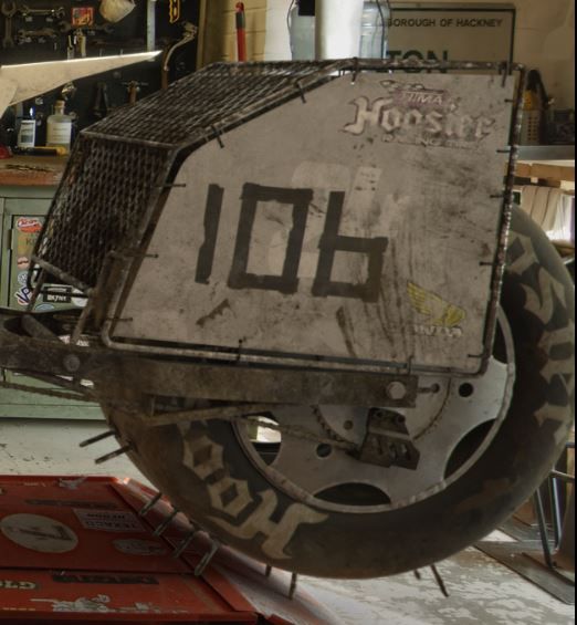
This was also the first time I had used cryptomattes, and they proved to be a game changer, saving countless hours of re-rendering passes. I primarily used cryptomattes to darken the bolts on the rear tire where the shadow was being cast, as they were too bright. Once I corrected this, the rear wheel suddenly sat in the shot a lot nicer. My main concern during this project was how well the asset would sit in the plate. No matter how well-integrated an asset is, if it doesn't sit naturally in the plate, it can feel out of place.
Bolts before and after tweak
I tried to match the camera properties of the backplate in my CG to enhance integration. While analysing the plate, I noticed several lens effects, including diffusion, chromatic aberration, vignette, and lens distortion.
Before and after lens effects
Another important lesson I learned during this project was to avoid undistorting and redistorting the footage at the start and end, as this degrades the quality. Instead, it's better to distort all the CG to match the plate.
Final Shot and Turntable
Final ShotTurntable
Thank you
Thank you so much for taking the time to read about my project! Thank you to The Rookies for reaching out and giving me the opportunity to share my workflow. Please reach out and connect with me if you’d like any further information on this project. Check out more of my work on my Rookies profile here.